Pages

Showing posts with label step-by-step. Show all posts

June 25, 2011

Step-by-step: Adding pitlane flags

Pitlane flags are nothing more that commands that tell the game how the cars should behave in and out of pitlane. Their position is very strict, so there's no secret in positioning them. Also, potential errors are displayed in GP4Builder at the Track Flags List window (Tools menu).

To add pitlane flags you need to go down to the command level, select "Add" and choose the relevant command. If you don't know what the command level is, refer to this tutorial, step 3. Here we suppose your pitlane is correctly positioned and complete until it rejoins the track.
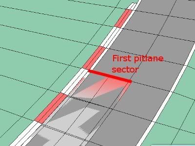


Step 1 - (AE) Corrects Pit Lines. The default command for starting the pitlane, always at the first pitlane sector. Normally you don't need to add it because it's already there.
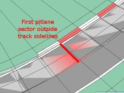


Step 2 - (9B) Pit Lane Start. This command should be placed in the first pitlane sector not fully contained inside the track sidelines. From this sector on, cars start following the pitlane centre line.
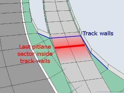


Step 3 - (9F) Pit Lane Fences Begin. This command should be placed in the last pitlane sector still inside the track walls. From this sector on, cars ignore the track walls and their movement is now limited by the pitlane walls.
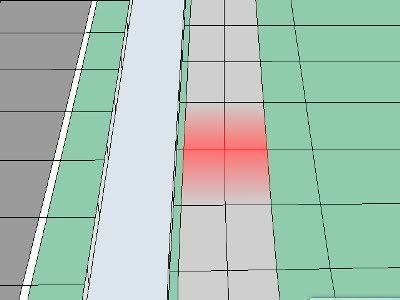


Step 4 - (96) Speed Limiter On. From this sector on, cars turn the speed limiter on. It doesn't have a specific place, although it must be after Pit Lane Fences Begin and before Pits Start commands.
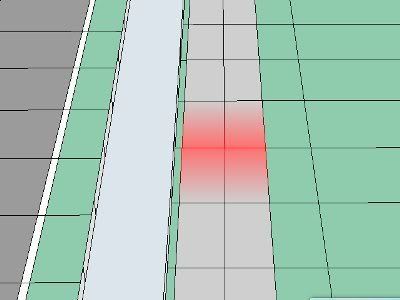


Step 5 - (89) Pits Start. This command marks the start of the teams' garages. It also doesn't have a specific place, but must be after the Speed Limiter On command.
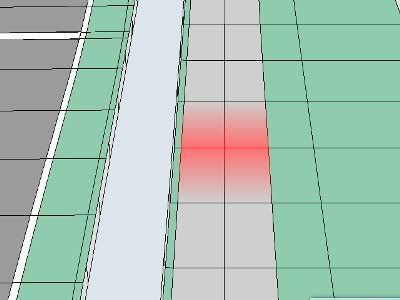


Step 6 - (F1) Pits End. This coomand marks the end of the teams' garages and must be placed exactly 33 sectors after the Pits Start command. Also, it must be before the Speed Limiter Off command.
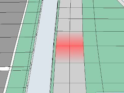


Step 7 - (97) Speed Limiter Off. From this sector on, cars turn the speed limiter off. It doesn't have a specific place, although it must be after Pits End and before Pit Lane Fence End command. The opposite of Speed Limiter On, basically.
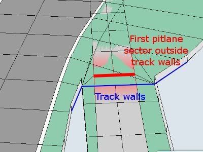


Step 8 - (A0) Pit Lane Fence End. The opposite of Pit Lane Fences Begin. This command should be placed in the first pitlane sector inside the track walls, when it starts rejoining the track. From this sector on, cars ignore the pitlane walls and their movement is limited by the track walls again.
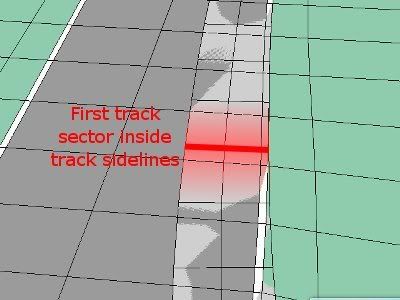


Step 9 - (9E) Pit Lane End. The opposite of Pit Lane Begin. This command should be placed in the first pitlane sector fully contained inside the track sidelines when it rejoins the track. From this sector on, cars stop following the pitlane centre line.
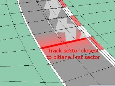


Step 10 - (86) Connect Pit Lane Start. This is one of the two commands not placed at the pitlane sectors, but at the track sectors instead. It should be placed at the track sector which is closest to the first pitlane sector. Also, it's very important that this sector and the first pitlane sector are perfectly aligned, or cars may get stuck at pitstops.
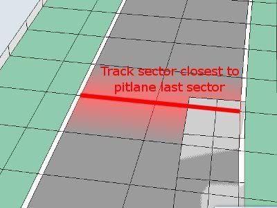


Step 11 - (87) Connect Pit Lane End. This is the other command not placed at the pitlane sectors. It should be placed at the track sector which is closest to the last pitlane sector. The sector with this command doesn't need to be aligned with the last pitlane sector.

Tip 1 - There are additional settings at track Magic Data that tell the game for how far behind the pitlane entrance they ignore cc-line and position themselves to enter the pitlane; and likewise, how far the cars should wait to follow the track cc-line after exiting the pitlane. These are the values 67 and 68 at Magic Data, labeled at "sectors to pit in 1" and "sectors to pit in 2" by default. These values are always relative to the sectors which have the Pit Lane Start and Pit Lane End commands.

May 30, 2011

Step-by-step: Understanding a .dat file

.dat files are the core files of GP4 tracks. Together with .col files, they dictate what you feel, while .gp4 and .bin files are responsible for what you see. Every track starts (or at least should start) with a .dat file, from which all other files can be created. This tutorial shows the structure of the .dat files inside GP4Builder, while each topic will be expanded later in further tutorials. The original .dat files are located in the Circuits folder.


Step 1 - Track Structure. Information stored in .dat files are divided as follows: Track sectors, Pitlane sectors, CC-Line, Track Cameras, GP4Info and Magic Data. These last two were created by the GP4 community and are optional, and Magic Data is the only one of them not (yet) editable in GP4Builder.


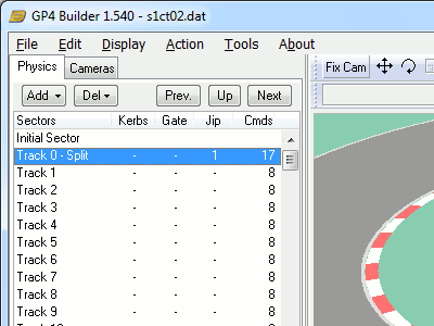
Step 2 - Sector level. Double-clicking "Track sectors" or "Pitlane sectors" opens the sector list for each case. Sectors define the track layout and must be spaced by exactly 4.8768 meters (16 feet). Here, basic data for the sectors can be edited, but the values themselves are stored in the next step.


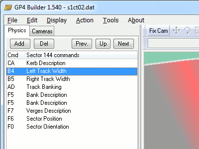
Step 3 - Command level. The sector list itself is just a list - all relevant data for the sectors is stored in the commands inside it - sector position, orientation, track width, banks width, banking, kerbs, track markings (called Jip mappings). Sectors usually have between 6 and 12 commands, with the most common value being 8.


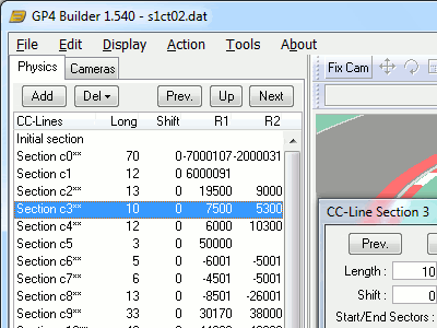
Step 4 - CC-Line sectors. Double-clicking "CC-Line" at Base level opens the cc-line sector list. It's composed of sectors of straights and turns which make the ideal line for cars to follow (CC stands for Computer Controlled). For making a cc-line, refer to this tutorial.


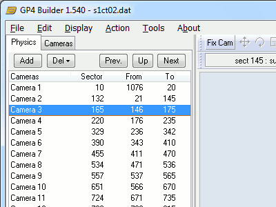
Step 5 - Track cameras. TV cameras, to be more specific. Here are specified the positions, coverage and settings like zoom of the various cameras around the track.


Step 6 - GP4Info. GP4Info contains additional info which is very useful for modded tracks, which include name, country, number of laps and position of split sectors. It can be accessed by opening the "Show GP4 Infos extended data" window at Track Initial Sector.


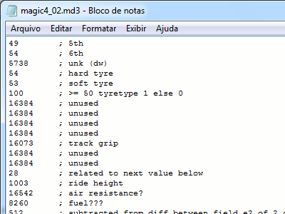
Step 7 - Magic data is a list of values which controls invisible settings like: default setup (wings, gears and brakes - for both player and CCs); pit strategies; behavior entering and exiting pitlane; CC performance finetuning; tyre types available; track grip; air density; and many more values, some of which still remain unknown. Magic data can be edited and applied to .dat files using CMagic.

That concludes this overview - these steps will be detailed more in the next tutorials.

March 08, 2010

Weekend party - Singapore


Imperfeições de asfalto e imprecisões de perfil talvez sejam os maiores desafios na reprodução fiel das condições reais do circuito de Marina Bay, em Singapura. Enquanto na maioria das pistas atuais a busca é por uma suavidade tamanha na mudança de nível, para este caso a perspectiva é bem diferente.
Por isso eu e Paulo conversamos sobre qual a melhor forma de sugerir toda a gama de solavancos e sobressaltos da pista e resolvemos elaborar esse eficiente método.

Tudo o que precisamos descobrir, de antemão, é que é muito melhor simular saltos alterando de forma randômica o perfil transversal do traçado (track banking) e não o perfil longitudinal ao longo do eixo. Então esse é o passo-a-passo do processo:

1. No GP4 Builder, crie livremente alterações de banking por toda a pista;
2. Exporte um banco de dados da pista com valores de inclinação transversal (Real Bank Values);
3. Copie esses valores para uma planilha do Office Excel;
4. Gere gráficos de linha para trechos da pista, em nosso caso, do setor 151 ao 200. Os gráficos servirão para acompanhamento das alterações propostas no passo 5;
5. Altere manualmente e de maneira randômica os valores de banking. A princípio, pequenas mudanças até estar habituado;
6. Salve o resultado como texto sem tabulações (.txt) e importe diretamente no GP4 Builder.

Pena que não sei como criar um vídeo, mas acredite, o resultado é muito bom e balança pra dedéu.

PS: Seria ainda melhor se o Laurent criasse uma ferramente de edição de banking assim como hoje existe para alteração de altura.


Urban tarmac imperfections and imprecise heights remains as one of the major challenges on simulating singapore marina bay circuit. As for most of tracks we search for the Best tarmac level and smoother track profile, at singapore there would be a whole opposite approach.

That´s why I´ve been talking to Paulo about it, and we decided to create such a brand new “method” for bumping making.

All I have to discover is the fact that, in GP4 Builder, it´s way better to simulate bumping by randomic changes for track banking, and not track heights (Z values) as we first previewed. So, this was the step-by-step process:

1. At GP4 Builder, create track banking changes all along the circuit;
2. Export a track database text for Real Bank Values;
3. Copy these values into a Office Excel Sheet;
4. Generate Graphics for sector ranges (as we chosen, from 151 to 200). These graphics will help on visualize changing proposed on step 5;
5. Manually and randomic alterations on TBnk0151 to TBnk200 values. It does not need to be such great changes, but enough to simulate tarmac bumps;
6. Save sheet as a .txt file and import at GP4 Builder.

Pity I´m not able to release a video of these changes here, but be sure it´s fine and shaking all around.

PS: It would be even better if Laurent Lo2k would create a Bank Profiler quite similar as available Track Profiler. Only difference would be the fact there would be positive and negative values and a central axis.

February 08, 2009

Step-by-step: Inserting a Google Earth picture

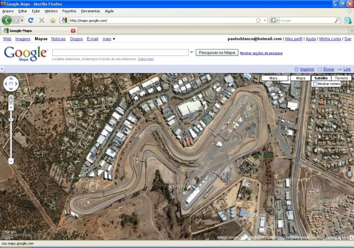
After a long hibernation, this section comes back with a subject asked quite a lot lately: how to insert a Google Earth picture in GP4Builder for track building. This tutorial requires an external image editing software of your choice.

Before we start, I shall remember that one of the reasons for the tutorial sleep was that I couldn't find much to talk about, so if someone has an idea for a new topic, just tell us!


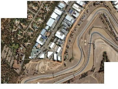
Step 1 - Obviously, find the track you wish. Use Google Maps instead of Google Earth, simply because Google Earth is round and Google Maps is flat, and we're going to use flat surfaces in GP4Builder.


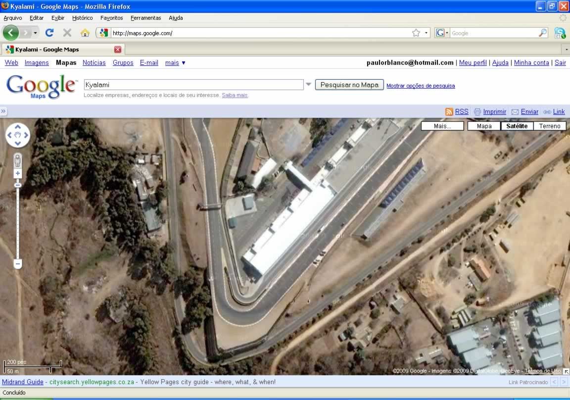
Step 2 - The closer the better, so zoom in until you get a good resolution. How good? An approximate measure is that track width on screen should be at least half of your fingers' width. Not precisely like that, just an estimate.


Step 3 - Resolution chosen, use an image editing software (Photoshop for example) and PrintScreen to set up a jigsaw with the track's pictures. Just take many screens and put them together with your software. The exact procedure varies between different programs, so I won't go deeper in this.


Step 4 - When you finish the jigsaw with the whole track and run-offs, and some buildings you believe are important, save the image as a 32-bit .tga file. Again how exactly this is done depends on your software, but shouldn't be hard to find.


Step 5 - Extremely important: how big is this map? Luckily, the guys at Google gave us a scale. Still using your image editing software, measure how many pixels is the meter scale. In this example, 50 meters equal 93 pixels.


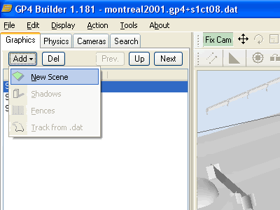
Step 6 - Back to the known, open in GP4Builder any track's .gp4 file and its corresponding .dat, for example, montreal2001.gp4 and s1ct08.dat - preferably choose a track that has the pitlane the same side as the track you're building. In the Graphics tab, double-click Scenes, then Add, New Scene.


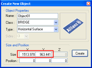
Step 7 - Now let's create the map object in GP4Builder. Click Add again, and New Object this time. Now we need that scale: in this example, my .tga file is 2816x1792 pixels big (which is a good size), how big should it's object be? Width-wise, it's 2816/93*50 = 1513.978. Same for height (1792/93*50), we get 963.441. So the object's size is 1513.978 width (X) and 963.441 height (Y). Put these values in the respect fields in the Size row. Finally, click Create.


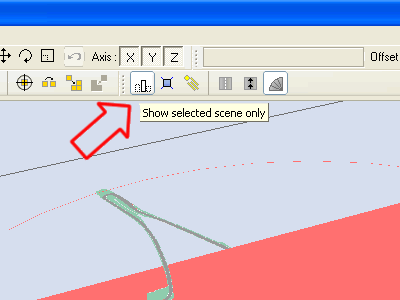
Step 8 - To see clearer, turn Show selected scene only on, or delete the remaining Scenes if you find it more convenient.


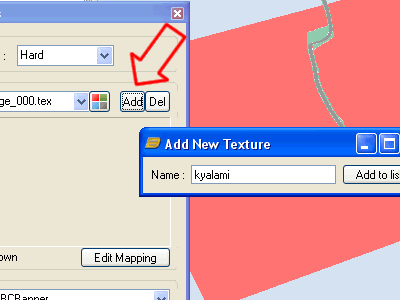
Step 9 - Open the newly-created object double-clicking its name on the object list on the left of the screen. In the window that opens, click Add and type your map .tga's filename in the Add New Texture window, then click Add to list. Just to remember, the .tga and .gp4 files must be in the same folder.


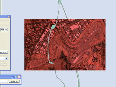
Step 10 - There is our map, ready to be a base for a .dat file, with all the realism we can get from a satellite photo.


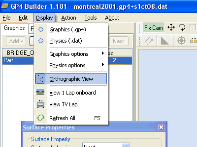
Tip - When building the .dat, turn Ortographic View and Fix Cam on, in Physics options turn Wireframe on and turn Plain off, and turn off Rotate/Zoom Mode in Preferences, Tools menu. This way you get the most of the picture, without the distortion of 3D-perspective.

Google Maps © 2009 Google, Imagery © 2009 DigitalGlobe, Cnes/Spot Image, GeoEye

March 30, 2008

Step-by-step: making a cc-line

On to the next tutorial, this one is a topic that every now and then appears at my mailbox: the cc-line! This process is much more brains than numbers, so I'll give some tips along the way. That said, let's get to work!


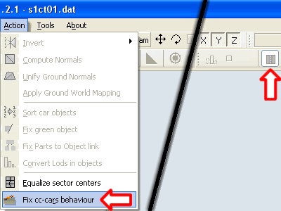
Step 1 - Before starting, open your .dat file and select Fix cc-cars behaviour from the Action menu. Also, turn on the cc-line display by clicking the Show CC-Line button on GP4Builder's toolbar (right arrow on the picture).


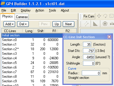
Step 2 - In the Physics tab, double-click CC-Line on the left of the screen. Select Initial section, Del, All Following Sections. Now you can start making the cc-line for your track.


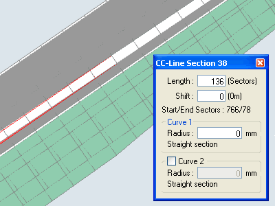
Step 3 - This is the initial section of the cc-line, the only one that's left. Length speaks for itself, Start Dfc is how much it is to the left or to the right of the track (here a value of 1024 equals 1 GP4 unit, 16 feet = 4.877 meters). Radius is the turn radius in milimeters, set it to zero if it's a straight. For a description of Angle and ShiftAngle refer to GP4Builder User Guide because we'll not be using them much here.


Step 4 - I want the cc-line to start in the right side of the track, so I set a positive value to Start Dfc (620 in this example), and I extended its length to 60 track sectors because there's a long straight to go. To go on, click on the Add button on the left of the screen, then Section.


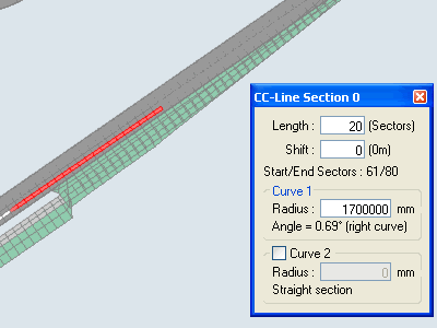
Step 5 - Now, let's make the cc-line go towards the right edge of the track as the first corner is a left-hander. This can be done slightly by setting a large radius, 1700000 over 20 sectors in this example. Remember this: a large radius gives slight, open turns while a small radius gives a tight, slow turn. Values smaller than 2000 are not of much use and may lead to game crashes. Negative values turn left and positive values turn right.


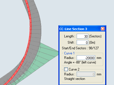
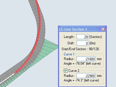
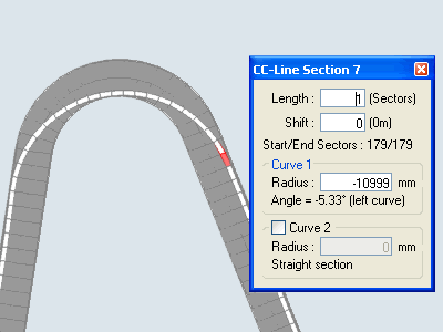
Step 6 - After a bit we arrive at the first corner. Cars aim to make the turn with the highest radius possible, so we need to do that. Set a lenght of more sectors than you'll need, then start playing with the radius until you hit the turn apex. If the cc-line goes off-track on the inside (like the picture), the radius is too small. If it goes off-track on the outside, the radius is too big. If it hits the apex correctly but does not hit the track edge on corner exit, then make the previous section one sector shorter and then adjust radius again.


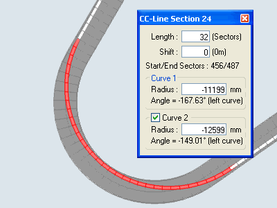
Step 7 - Notice that, in my solution, I checked the Curve 2 checkbox. This means that instead of a circle, this cc-line section will follow an ellipse in which the two radii values are actually the two semiaxes of that ellipse. No good at maths? Well, the only thing you need to know is that the cc-line section will start with the Curve 1 radius and finish with the Curve 2 radius. In this example, the cars will accelerate as the turn goes on because the radius increases. Sections with decreasing radius should be avoided unless they're really necessary.


Step 8 - When you reach the start/finish line again, make the last cc-line section go after the line, and make its end contact with the first cc-line sectors as close as you can. You may need to adjust previous sectors to achieve that. You'll only know if your cc-line is good enough by watching computer cars driving in game, so be sure to test a lot until you're really satisfied with the results.


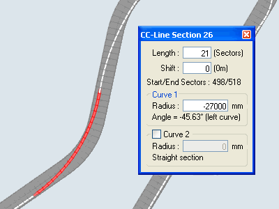
Tip 1 - There are some corner combinations that make you sacrifice the first corner in order to have a better line for the second one, like the left-right in this picture. The radius of the left turn is just enough to get a good line in the right corner that follows. So always make the cc-line looking at what you have in the following sectors. Onboard videos are very useful if you're working on a real track.


Tip 2 - Do not use two cc-line sections in the same corner. This can make cc-cars brake mid-corner when they approach the second section. This can be avoided by using the Curve 2 option correctly.


Tip 3 - Sometimes you may need to use very small cc-line sections to make an adjustment, for corner entry for example. This will not cause the problem from Tip 2 if the section is short enough for cc-cars not to hit the throttle again, so they will not brake a second time to enter the following section.


Tip 4 - A cc-line can be improved as you progress on your track, for example, kerbs, elevations and banking may change the best way to approach a corner. Specially kerbs! So don't be afraid to do your cc-line all over again, if it's for better. Even the ones from GP4 original tracks can be improved, keep that in mind.

There it is, also remember that pitlane does not have a cc-line of its own, instead the pitlane commands guide the cars through pitlane. The .dat file I used to make this tutorial is available in our downloads section, in the Unfinished .dats folder. See you later!